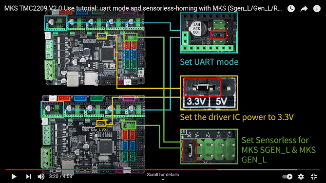
MKS Gen L V2.1 and TMC2209 stepper motor drivers
Step/Dir and UART mode experiments for MKS GEN L V2.1 board with TMC2209 stepper motor driver.
Do not plug/unplug drivers or steppers while the board is energized. Disconnect power prior to connecting any motors during setup. Failure to do so may fry the board.
Problem: I would like to, for the first time, control motor with aforementioned hardwares.
- TMC2209 uses Step/Dir mode, with simple example from TMCStepper library.
- TMC2160 use Step/Dir mode , with simple example from TMCStepper library. (next post)
More problem:
- If I can use StallGuard, CoolSteps, Silent mode, it will be better. However, if I do so, I need to rewrite the code for interfacing with ROS (Robot Operating System)
- I would like to use basic setup for both driver with DIR/STEP method, and interface with ROS. To do so, May I use AccelStepper library?
- During the test TMC2160 with big motor Nema23: 23HS45-4204S, I found that the motor temperature reaches 52 degree. Can I use coolsteps , as the name may imply, to control this temperature?
-- My answer: Datasheet said it is possible, it needs SPI mode. I may comeback to solve this problem after I can build the whole robot. I will first focus on basic robot setup, even with 50 degree temperature. For the time being.
Term: Mobo: Motherboard
Experiment
TMC2209 Dir Stepper Connection
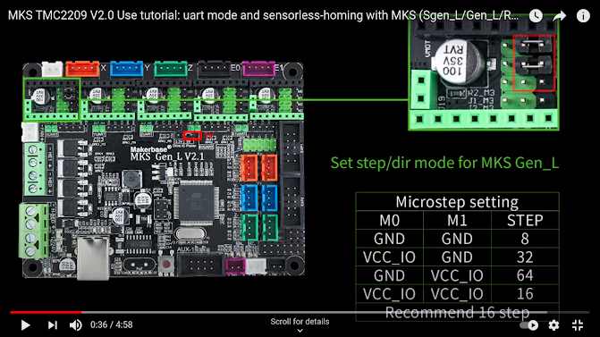
Picture 1: Step/DIR setting for TMC2209 with MKS gen L V2.1
TMC2209 is connected to Hanpose 17HS3401S stepper motor at Mobo's X position. According to the stepper's datasheet, the current per coil is 1.3A , I need the following setting
- Microstep 16. Therefore I choose exactly the same microstep jumper setting as Picture 1.
- Max current. For safety factor of 0.8, I need to set Max current to 1.0A per coil. This can be done by adjusting potentiometer on TMC2209 board. Measure potentiometer voltage w.r.t board ground, called VREF. Board ground is on USB female metal case. See Picture2
I still don't understand when to set this IRUN/IHOLD programatically with UART, or ignore them and use analog VREF like Picture 2. My current understanding is that DIR/Step mode: Use Vref analog
Picture3. TMC2209 connection
TMC2209 UART connection
Current Setting can be done by Software. Therefore, just write the code to set max current to 1A.
Programming: Use TMCstepper library
=================================
#define DIAG_PIN2209 3
#define EN_PIN2209 38//30 for E1 //38 for X //62 for Z// Enable //Check pinout detail diagram E0=1,E1=2,X=3,Y=4,Z=5
#define DIR_PIN2209 55// 34 for E1//55 for X//48 for Z//Direction //Check pinout detail diagram
#define STEP_PIN2209 54// 36 for E1// 54 for X // 46 for Z //Step //Check pinout detail diagram
#define EN_PIN2160 62//30 for E1 //38 for X //62 for Z// Enable //Check pinout detail diagram E0=1,E1=2,X=3,Y=4,Z=5
#define DIR_PIN2160 48// 34 for E1//55 for X//48 for Z//Direction //Check pinout detail diagram
#define STEP_PIN2160 46 // 36 for E1// 54 for X // 46 for Z //Step //Check pinout detail diagram
================================
To check the pinout, refer to this two pictures.
Look at Schematic for Digital pin number. E0,E1,X,Y,Z = 1,2,3,4,5


ความคิดเห็น
แสดงความคิดเห็น